Follow us on the social network

Process Safety
services include the investigation of explosions in the Chemical Process Industries and the implementation of design changes, process safety studies and HAZOP reviews.
Thin Film
Technology Highlights:
Evaporating/Distilling/Crystallizing
Improving performance and safety of thin-film evaporators con figuration and control enhancements boost effectiveness.
Chemical Processing, February 1996 - Rocky C. Costello, P.E.
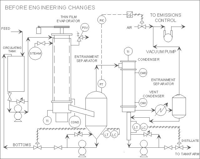
Many Resource Conservation and recovery Act (RCRA) treatment, storage and disposal facilities use thin-film evaporators and fractional-distillation systems to separate reusable solvents from contaminants. However, the performance and/or safety of these evaporator systems can be compromised by inadequate temperature control, excessive vacuum, and the drawback of air into flammable-solvent vapors when the vacuum source is turned off. This article offers advice on avoiding these three common evaporator system problems.
Optimizing Temperature Control
Inadequate temperature control during the processing of heat-sensitive, reactive or polymeric type materials can result in excessive downtime. The possibility of polymerization increases when these materials are continually exposed to elevated temperatures. If polymerization occurs, the evaporator can clog with polymer and, in some cases, the rotor can be frozen in place by the polymerized material. Although solvent can be used to dissolve the polymer if a suitable solvent can be found, severe clogging can require removal of the rotor and hydroblasting of both rotor and barrel to remove the polymer.
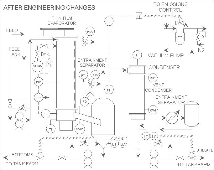
Changing the configuration of the thin-film evaporator from one which recirculates around the feed tank to a once-through flow will alleviate the continuous exposure of process materials to elevated temperatures. The process flow should be from the feed tank to evaporator to bottoms tank.
Evaporator temperature control is also essential to prevent overheating of materials. Normally, it is not adequate to manually control steam flow to the evaporator steam jacket through a valve. A cascade control loop can be used for better temperature control.
In a cascade control loop, a temperature transmitter at the bottom of the column below the heated section sends a signal to a temperature indicating controller (PIC). The PIC, in turn, receives a signal from the pressure transmitter mounted on the steam jacket and then throttles the pressure control valve on the steam line. Lower pressure steam means lower process fluid temperature and higher temperature and higher pressure steam means higher process fluid temperature.
An example is an electronic temperature controller with proportional, reset and derivative functions. Similarly, the pressure controller is of the same type with the exception that the input is the digital signal from the temperature controller. The 4-20 mA output signal from the pressure controller is fed to a current/pneumatic transducer. The 3-15-psig signal leaving the I/P transducer throttles the steam valve. The actuator on the steam valve fails closed.
Preventing Excessive Vacuum
Excessive vacuum can produce too much vapor flow for processing by the emissions control system. Control of the vacuum can significantly decrease emissions.
A pressure control loop can be used to set the operating pressure for the system, but the method of control for the level of vacuum has a marked effect on the flow through the emissions control system.
For example, with a pressure transmitter located on the entrainment separator, the controller receives a signal from the pressure transmitter and throttles an air bleed valve on the suction side of the vacuum pump. This style pressure control maintains a constant full flow through the vacuum pump to the emissions control system (at200 cfm, for a 200-cfm, liquid ring-type vacuum pump with an external cooler on the pump fluid).
Air drawback into the evaporator after vacuum pump is shut down can result in unsafe conditions when flammable solvents are distilled A flammable mixture can be created in the equipment that is a potential source for an explosion.
If the air bleed valve is changed to an air bypass-type valve that circulates air around the pump, the air through the pump is still maintained (at 200 cfm). The flow to the emissions control system is reduced to as low as the inward air leakage rate to the thin-film system. On startup, the flow would be near the full capacity of the pump and slowly decrease to the inward air leakage rate.
The air bypass valve (for the example) is of the diaphragm stem seal type, chosen to prevent fugitive emissions from leaking around the stem. The differential pressure across the valve (for sizing) is basically the discharge pressure of the pump. The valve has a 3-15-psig actuator and is of the fail-open configuration. With the fail-open configuration, the boil-up would simply stop upon the loss of instrument air. Had a fail-closed configuration been used, the lower operating pressure would lead to rapid boil-up.
|
LEGEND |
|
|
COND Condensate |
PIC Pressure Indicating Controller |
|
CWI Cooling Water Inlet |
PSV Pressure Safety Valve |
|
CWO Cooling Water Outlet |
RD Rupture Disc |
|
I/P Current to Pressure Transducer |
TI Temperature Indicator |
|
LC Level Controller |
TIC Temperature Indicating Controller |
|
LT Level Transmitter |
|
|
P/I Pressure to Current Transducer |
TT Temperature Transmitter |
Minimizing Air Drawback
Air drawback into the evaporator after the vacuum pump is shut down can result in unsafe conditions when flammable solvents are distilled. A flammable mixture can be created in the equipment that is a potential source for an explosion.
To eliminate the potential safety hazard, a nitrogen or inert gas pad regulator can be installed on the discharge of the vacuum pump and set for 2 in to 3 in of water pressure. While the vacuum pump is operating, the discharge pressure would be much higher than 2 in to 3 of water pressure, thus no nitrogen would be bled into the system. Upon shutdown, the pressure would be bled into the system. The regulator must be accurately sized to provide the proper flow of nitrogen into the unit.
It is essential to consider how quickly the process equipment should be padded, in seconds or minutes, and the pump discharge rates. In the example, the flowrate of the distillate pump anf the bottom pump must be added together and converted to cubic feet per minute. The inward gain flow equals the regulator flowrate minus the total pump discharge flowrate. The inward gain flow divided by the volume of the process equipment in cubic feet gives the padding time.
In some cases, it may be desirable to have an automatic shutoff valve on the discharge of the vacuum pump beyond the nitrogen regulator. The valve would be open while the vacuum pump is running and closed while the vacuum pump is off. The shutoff valve would ensure that only nitrogen and minimal air would enter the system following shutdown of the vacuum pump.
It is important to take into consideration that the valve be fully ported and not create any restriction on the flow from the vacuum pump. Depending on the type of pad regulator may have a separate pilot line tube on it. In this case, the sensing pilot tube can be connected to the discharge of the vacuum pump. Thus, the gas does not have to flow backwards through the pump.
If nitrogen is piped to each of the individual process vessels, there is a potential to create more vacuum leaks. Using all welded pipe for the gas line or tubing instead of screwed connections can minimize vacuum leaks.
A pressure relief valve installed on the evaporator ensures the process equipment does not overpressure if the pad regulator fails. A suitable rupture disc installed between the relief valve and the evaporator is a good practice. All wetted parts of the rupture disc and holder device must be compatible with the process fluids.
Please call for further information
R.C. Costello & Assoc., Inc.
1611 S. Pacific Coast Highway, Suite 302
Redondo Beach, CA 90277
Tel: (310) 792-5870, Fax: (310) 792-5877
E-MAIL: rcca[at]rccostello.com
COSTELLO
Consulting Engineers
- Explosion Investigations
- Hazards Analysis
- Published Article 1 (Flashback Prevention)
- Published Article 2 (Thin Film)
- Definitions